Spline Modeling in Cinema 4D: Lathe
What This Tutorial Covers
Spline Drawing
Vector profiles that drive 3D geometry.
Lathe Generator
Revolve a spline around an axis to create rotational forms.
Use Cases
Bottles, vases, cups — anything radially symmetric.
Noble Desktop's Video Editing & Motion Graphics Certificate teaches Cinema 4D alongside After Effects, Premiere Pro, and motion design fundamentals.
Unlock the intricacies of Cinema 4D with this comprehensive guide, covering topics like Creating Splines, Spline Modeling Techniques, Transforming 3D Models, and more. Learn how to create a 3D model from scratch using various techniques and tools.
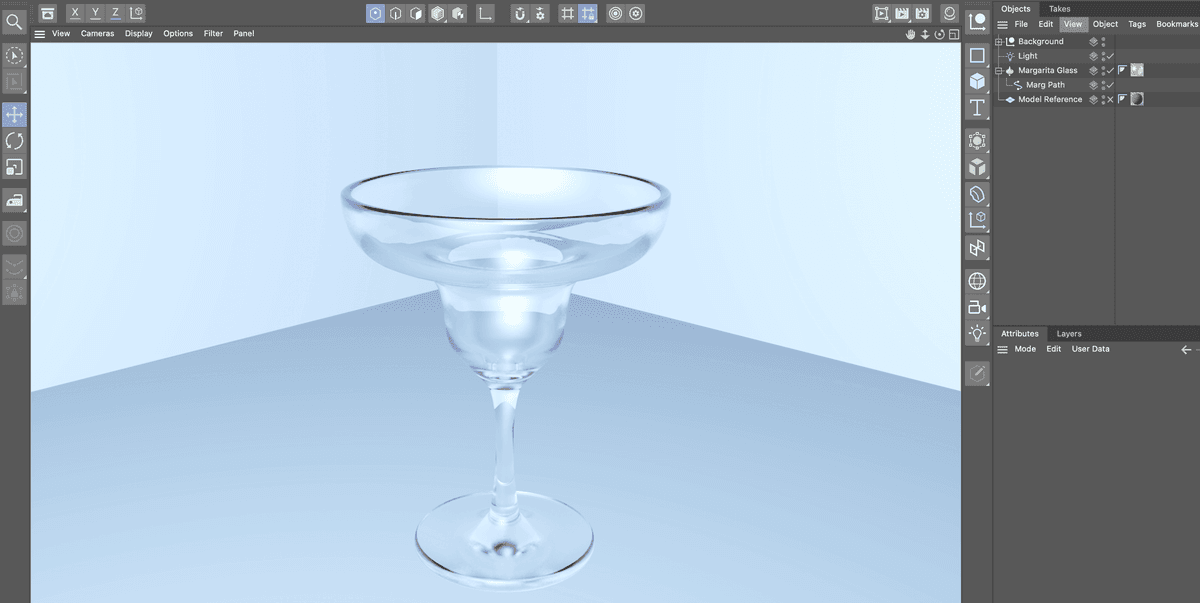
Exercise Preview
Types of Spline Objects
In the Create menu, press and hold (long press) on the Rectangle to reveal the other shapes available to you.
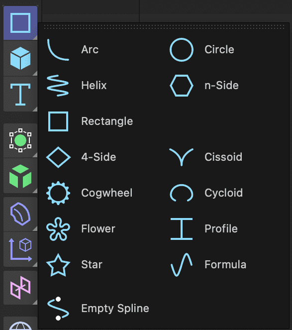
Cinema 4D Lite can create a wide range of primitive spline objects: Arc, Helix, Rectangle, 4-side, Cogwheel, Flower, Star, Circle, n-Side, Cissoid, Cycloid, Profile and Formula. Additionally, custom spline objects can be created using the Spline Pen  .
.
Creating a Reference for Modeling
When modeling it is usually helpful to have some type of drawing as a reference. A helpful technique is to use your reference as the texture on a plane and then use that as your reference.
In the Create Menu press and hold the Cube button to reveal the other primitive shapes.
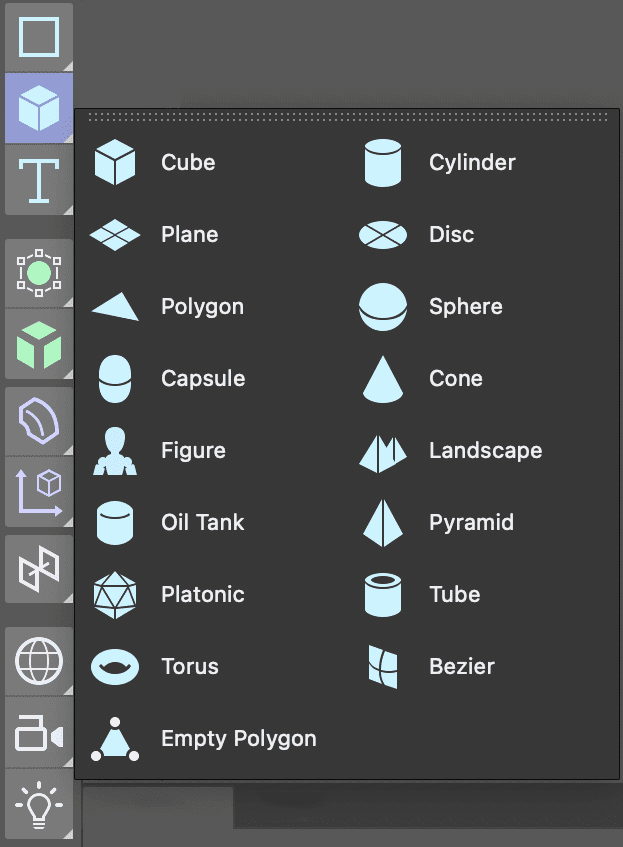
Select the Plane object from the list.
In the Perspective viewport click on the Toggle Active View
 button to reveal all four viewports.
In the Object Manager double–click on the Plane and rename it Model Reference.
With the Model Reference object selected click on the Coord. tab in the Attribute Manager.
Change R.P to 90
This will rotate the plane so it faces forward in the Front view.
Still in the Attribute Manager click on the Object tab and change:
- Width to 1080
- Height to 1920
NOTE: Why are we using 1080 X 1920 for the size of the plane. Those are the dimensions of the image we are going to use as a reference. Creating a plane so it’s the same siaze as your reference image will avoid problems later.
Click in the Front view and press H or choose View > Frame Geometry.
- Repeat this for the other viewports.
In the Front viewport choose Display > Gouraud Shading. This will allow us to see the texture in the Front viewport once we apply it.
Click on the Material Manager
 button to open it.
Click on the New Default Material
 button.
Double–click on the new material’s name and rename it Model Reference.
- Press Return (Mac) or Enter (Windows) or click on any empty space to finalize the name change.
Double–click on the material’s icon
 to open the Material Editor.
In the Material Editor turn off the switch next to Reflectance.
Click on the Color map to make sure it’s active.
Click the arrow next to texture and choose Load Image.
Navigate to C4D in AE Class > Creating 3D Models > Media > Images.
Double–click on Reference—Margarita Glass.png. Click No in the dialog that appears.
NOTE: Becasue this image isn’t in the same root folder as our C4D file the application gives us the opportunity to make a copy of it there. This way we are less likely to misplace or move the files which would result in problems rendering later.
Close the Material Editor.
Drag the material from the Material Manager onto the Model Reference plane in the Object Manager.
Click the Material Manager button again to close it.
In the Object Manager click on the Model Reference object to select it.
In the Attribute Manager click on the Coord. tab.
Change the P.Z attribute to 100
This places the plane behind the spot in the scene where new objects are created and should make tracing it later a bit easier.
In the Front viewport, click the Toggle Active View
to hide the other views. We are going to create our model entirely in the front view.For better organization we are going to place the reference image on its own layer.
- In the Object Manager CTRL–click (Mac) or Right–click (Windows) on the Model Reference object.
- Choose Add to New Layer. Notice that the little shape to the right of your object’s name lights up.
Locate the Layer Manager, it’s the panel named Layers.
- Double–click the new layer and rename it Reference.
- Click on the lock located beneath the L label.
NOTE: Each of the letter labels controls a diffrent property of the layer, the S solos the layer content, the V controls its visibility, etc. To see what each label represents choose open the View menu in the Layer Manager.
Click back on the Attribute Manager tab to reveal it. When a layer is selected this panel allows you to set its options.
Press Cmd–S (Mac) or CTRL–S (Windows) or choose File > Save Project.
Click on the Spline Pen
tool to the left of the viewport.In the Front view, hold the 2 key on your keyboard and drag the Left Mouse button to zoom in until you can comfortably see the reference image.
Click at the blue center line where it crosses over the center of the glass to create the first vertex, then click to create a second vertex about half way up the interior of the glass.
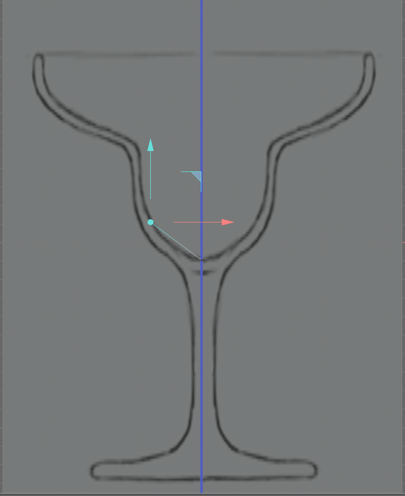
Continue to create a series of straight lines until you have the rough contour of the glass created.
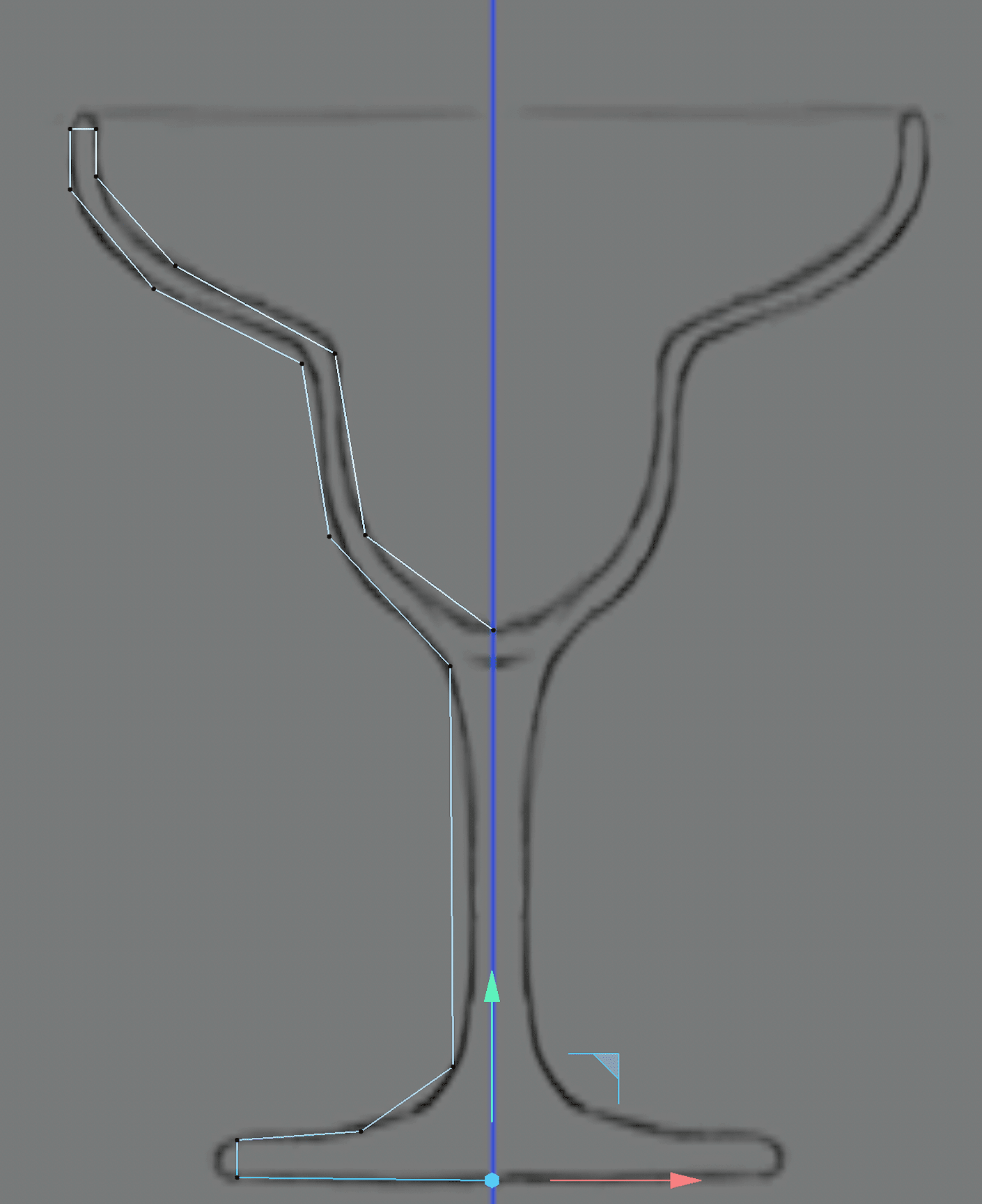
Press the Esc key on your keyboard to finalize the spline.
Press the Spacebar on the keyboard to switch to the Live Selection
 tool.
tool.Drag the live selection tool over all the vertices on the spline to select them.
NOTE: The vertices turn white when they are selected.
CTRL–click (Mac) or Right–click (Windows) on one of the selected vertices and choose Soft Interpolation.
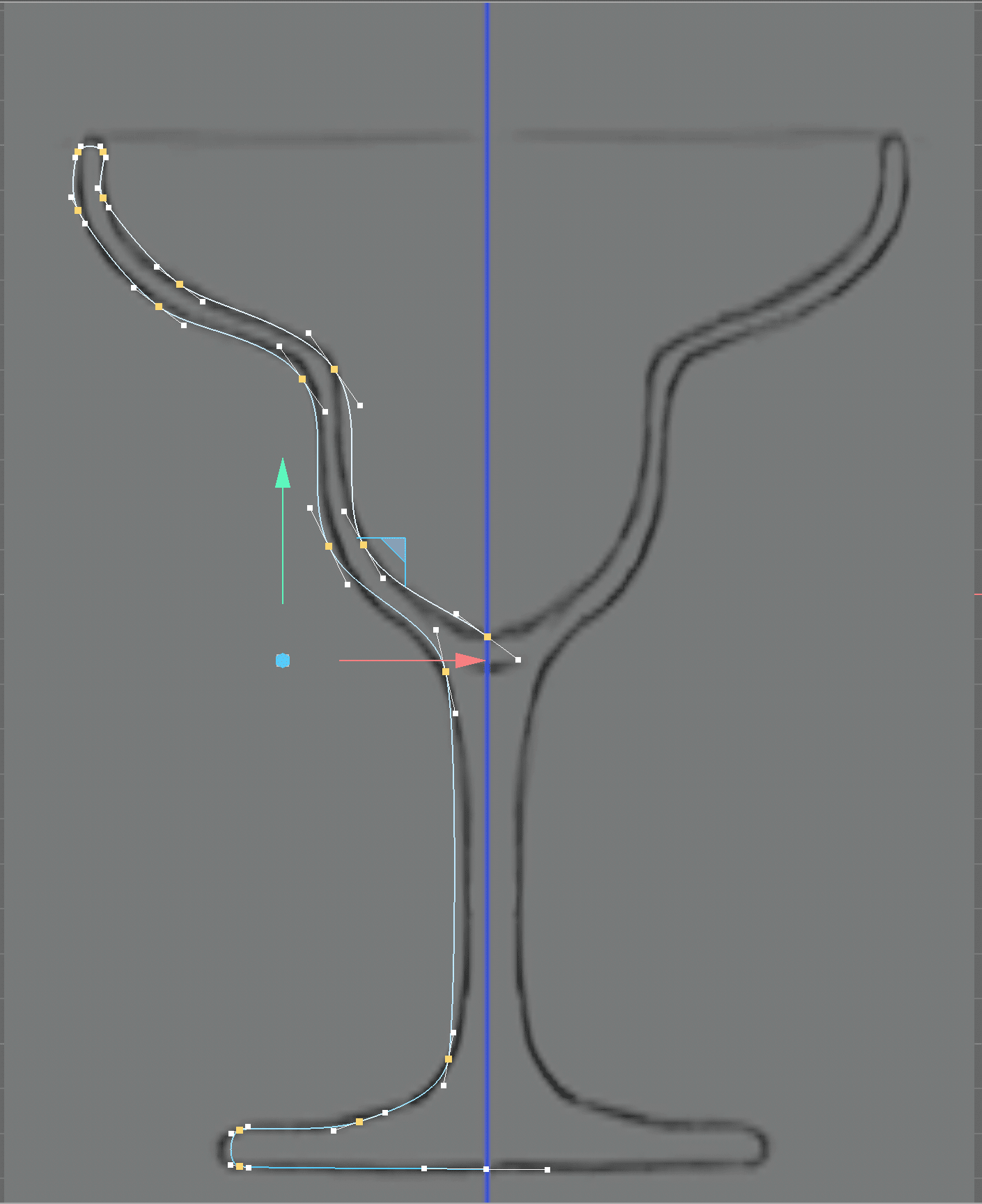
Press E to activate the Move tool.
Click on the vertex at the center line along the top of the glass.
Drag this vertex’s tangent lines until the curve looks more like the reference image.
NOTE: You can also use the Move tool to move vertices around.
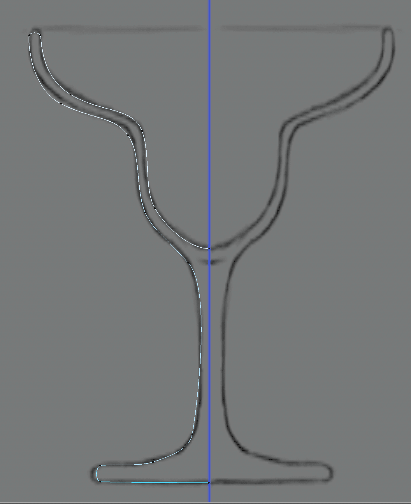
Continue to adjust vertices and tangents until you are happy with the results.
NOTE: To break Tangents so they are no longer linked together hold the Shift key while dragging. To delete a vertex, select it and press Delete (Mac) or Backspace (Windows) on your keyboard.
Press Cmd–S (Mac) or CTRL–S (Windows) or choose File > Save Project.
In the Object Manager click off the check mark to the right of Model Reference to hide it.
Still in the Object Manager double–click on the Spline object and rename it Marg Path.
Hold the Option (Mac) or ALT(Windows) and click on the Subdivision Surfacemodifier in the Createtools and choose Lathe**.
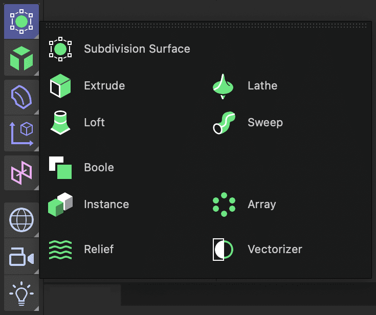
NOTE: Holding down the keyboard modifier key adds Lathe as the parent of the currently selected object. This automatically applies it to create the new shape.
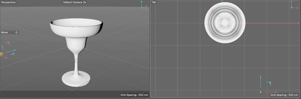
Click on the toggle Active View
button to view all four viewports.In the Perspective view, adjust the window until you can see the top of the glass clearly.
NOTE: You can hold down the 1,2, & 3 keys on the keyboard and drag in the window with left mouse buttons to use the Move, Scale, and Orbit camera tools.
The shape of the glass is a little rough, we can fix this using the Subdivision attribute in the Lathe object.
In the Object Manager, double–click on the Lathe object and rename it Margarita Glass.
- Press Return (Mac) or Enter (Windows) on the keyboard to finalize the change.
With the Margarita Glass object selected click on the Object tab in the Attribute Manager.
Change Subdivisions to 50. This will give the glass a smoother look.
NOTE: If you need to adjust the spline more you can just turn off the lathe object, click on the spline and use the move tool to adjust it. Remember to turn the lathe back on when you are done.
Click in each other viewport and press H on your keyboard to fit the geometry in the view.
In the Front view choose Display > Lines.
NOTE: You can also hold the N key on the keyboard and press G to switch to the lines display mode.
Press Cmd–S (Mac) or CTRL–S (Windows) or choose File > Save Project.
Creating Lights
The default lighting in the C4D scene isn’t bad, but for the glass material we are going to add in a bit our own custom lights should work better.
Long press on the Light object to reveal the light types you can create.
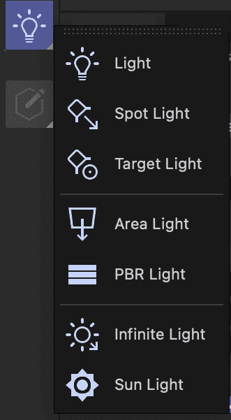
Choose Light from the list to create a default omni directional light.
Press E to activate the Move tool.
In the Top and Perspective views move the light around so it fully illuminates the front (based on your perspective view) of the glass.
Click in the Perspective view to make it active.
Press and hold the Render View
 button at the top of the viewports.
Choose Interactive Render Region.
Adjust the render region in the Perspective view so that is covers the entire glass.
Adjust the quality slider to whatever your computer can preview well.
Click on the Perspective window’s Toggle Active View
button to make it the only viewport.Click on the Light in the Object Manager to select it.
Click on the General tab in the Attribute Manager.
Make sure the light color is set to HSV and set:
- H : 215
- S : 40
- V : 90
This gives the light a blueish color and helps to cool off the entire scene.
Press Cmd–S (Mac) or CTRL–S (Windows) or choose File > Save Project.
Creating and Adding Textures
In this part of the lesson, well make a glass texture to apply to the margarita glass.
CLick on the Material Manager
button to open it.Click on the New Default Material
button.Double–click on the new material’s name and rename it Glass.
- Press Return (Mac) or Enter (Windows) or click on any empty space to finalize the name change.
Drag the Glass material onto the Margarita Glass Lathe object in the Object Manager.
Double–click on the material’s icon
to open the Material Editor.Click on the Color map to make it active.
Make sure the color mode is set to HSV and change the color so that:
- H = 200
- S = 64
- v = 100
Click on the witch next to Transparency to enable it.
Click on Reflectance to make it active.
Click the Remove button at the top of the reflectance attributes to delete the default reflection map.
Click Add and choose Beckman from the list.
Click on the arrow next to Layer Fresnel and set:
- Fresnel : Dielectric
- Preset : Glass
- Strength : 85
- IOR : 1.5
In the Beckman attributes above set:
- Roughness : 46
- Reflection Strength : 92
- Specular Strength : 33
Close the Material Editor and Material Manager
Turn off the *Interactive Render Region.
Press Cmd–R (Mac) or CTRL–R (Windows) to render the perspective view.
Press Cmd–S (Mac) or CTRL–S (Windows) or choose File > Save Project.
You can close this project now. You have completed this section of the lesson.