Spline Modeling: Loft
What This Tutorial Covers
Spline Profiles
Cross-section curves at multiple stations.
Loft Generator
Skin geometry across the spline profiles.
Modifying Shapes
Tweak splines and watch the loft update live.
Noble Desktop's Video Editing & Motion Graphics Certificate teaches Cinema 4D alongside After Effects, Premiere Pro, and motion design fundamentals.
Discover the essentials of 3D modeling with this in-depth Cinema 4D tutorial, covering diverse topics such as creating splines, shapes and lines, and using the loft generator to create complex and organic shapes.
Exercise Preview
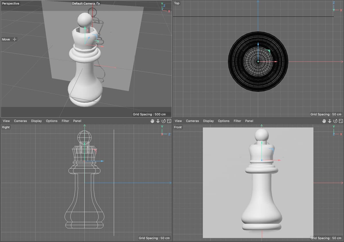
Creating a Modeling Template
To save time in this lesson we have gone ahead and set up a reference for you to model from. It’s just a simple plane with an image texture but the template it provides makes it easier to create your 3D model. When modeling it is usually helpful to have some type of drawing as a reference. A helpful technique is to use your reference as the texture on a plane and then use that as your reference.
If you need to recreate your own you can follow these general steps:
In the Create Menu press and hold the Cube button to reveal the other primitive shapes.
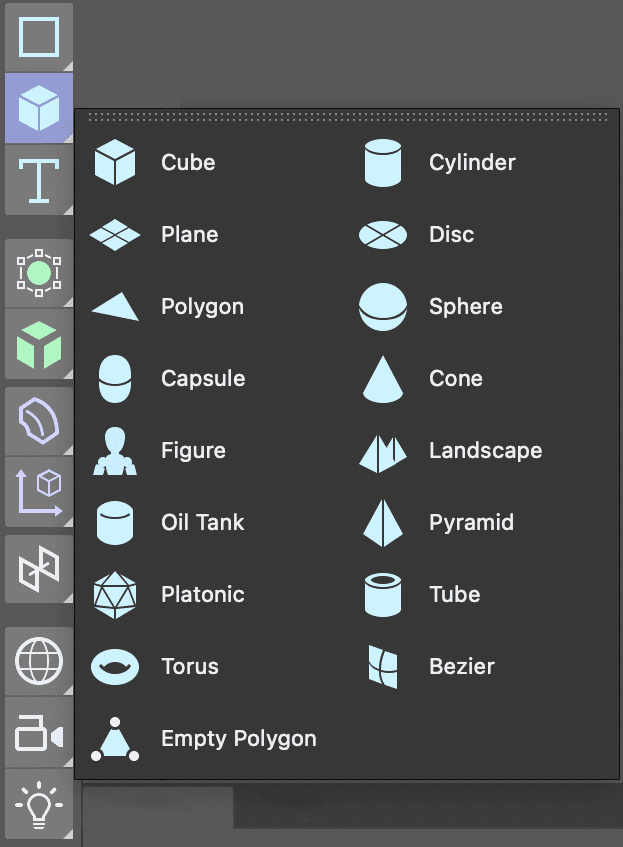
Select the Plane object from the list.
In the Perspective viewport click on the Toggle Active View
 button to reveal all four viewports.
In the Object Manager double–click on the Plane and rename it Model Reference or another name that wil make it easier for you to locate this object later.
Rotate the plane until it is facing towards you in the Front view.
In the Attribute Manager click on the Object tab and change the plane’s dimensions to match those of the image you are going to use as a reference.
NOTE: Since the default behavior of a material applied to an object is to stretch to fit it creating a plane so it’s the same siaze as your reference image will avoid distortions later.
Click in the Front view and press H or choose View > Frame Geometry.
- Repeat this for the other viewports.
In the Front viewport choose Display > Gouraud Shading. This will allow us to see the texture in the Front viewport once we apply it.
Click on the Material Manager
 button to open it.
Click on the New Default Material
 button.
Double–click on the new material’s name and rename it Model Reference.
- Press Return (Mac) or Enter (Windows) or click on any empty space to finalize the name change.
Double–click on the material’s icon
 to open the Material Editor.
In the Material Editor turn off the switch next to Reflectance. Having a refelctive model template can be very distracting.
Click on the Color map to make sure it’s active.
Click the arrow next to texture and choose Load Image.
Navigate to the image to use as your reference and double–click on it.
NOTE: If you image isn’t in the same root folder as your C4D file the application gives you the opportunity to make a copy of it there. This way you are less likely to misplace or move the files which would result in problems rendering later.
Close the Material Editor.
Drag the material from the Material Manager onto the Model Reference plane in the Object Manager.
NOTE: You can also drag a material directly onto your model in one of the viewports.
Close the Material Manager.
In the Object Manager click on the Model Reference object to select it.
Use the Move tool to push your reference image behind the origin. This way you wil be able to see the objects you create without them intersecting the plane.
For better organization we are going to place the reference image on its own layer.
- In the Object Manager CTRL–click (Mac) or Right–click (Windows) on the Model Reference object.
- Choose Add to New Layer. Notice that the little shape to the right of your object’s name lights up.
Locate the Layer Manager, it’s the panel named Layers.
- Double–click the new layer and rename it Reference.
- Click on the lock located beneath the L label.
NOTE: Each of the letter labels controls a diffrent property of the layer, the S solos the layer content, the V controls its visibility, etc. To see what each label represents choose open the View menu in the Layer Manager.
Click back on the Attribute Manager tab to reveal it. When a layer is selected this panel allows you to set its options.
Press Cmd–S (Mac) or CTRL–S (Windows) or choose File > Save Project.
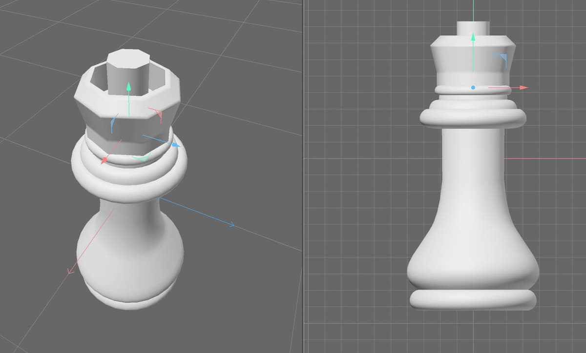
Creating a Loft
In order to create a loft you have to create a series of closed splines (shapes) so that the Loft generator can create an outer surface or skin that connects them.
Use the Create menu to create your first shape.
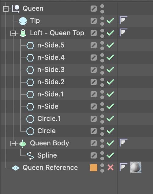
In our example graphic, we made the base shape of the Queen’s crown a circle.
Use the Create menu again to create the Loft generator.
In the Object Manager drag the first shape you created into the Loft object.
- Double–click on the Loft and rename it so you will be able to identify it later. We called ours Queen Top
Create another shape and in the viewport, position it above the first shape in the loft.
Technically, you can loft in any direction, you can even rotate shapes to create bends and turns in your object. For the chess piece example we will build upwards.
In the Object Manager add this new shape to the loft.
Continue to add shapes to the loft until it matches your desired appearance. In the example model a combination of circles and n-sides (polygon) were used to create the chess piece seen in the example.
Press Cmd–S (Mac) or CTRL–S (Windows) or choose File > Save Project to save your C4D project.