The Ellipse & Polygon Tools
What This Tutorial Covers
Ellipse Construction
Draw by axis endpoints or center + radii.
Regular Polygons
Inscribed or circumscribed n-sided shapes.
Closed Geometry
Both produce closed polylines for hatching.
Noble Desktop's AutoCAD Certification teaches 2D drafting, 3D modeling, and the production drawing workflow architects and engineers rely on every day.
Learn how to effectively use the Ellipse and Polygon tools in AutoCAD through this comprehensive tutorial, featuring step-by-step exercises and visual aids.
Exercise Preview
Where to Access the Ellipse Tool
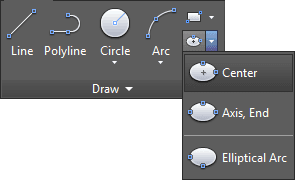
You can enter options for the Ellipse tool with the keyboard through the Command Line, or use the Ellipse drop down menu in the Draw Panel on the Ribbon. You can also access options for the Ellipse tool from the Draw menu.

Using the Ellipse Tool
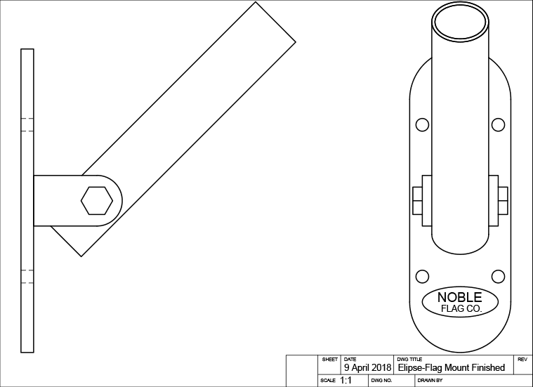
Open the file Ellipse-Flag Mount.dwg.
You will start by making an ellipse around the Noble Flag Co. Logo. The logo itself will interfere with Object Snap when you make the ellipse, so you’ll need to hide it. Start the Layer Freeze tool and click on the logo to freeze the Text layer and hide the logo.
Select the Center option on the Ellipse tool
 . An ellipse has two axes. Using the Center option means that the first axis will be a radius, established from the center to edge of the ellipse. Click on the center point of the bottom arc of the front view to specify the center of the ellipse. Pull left or right along the X-axis and enter a radius of .75. Keep the Ellipse command open.
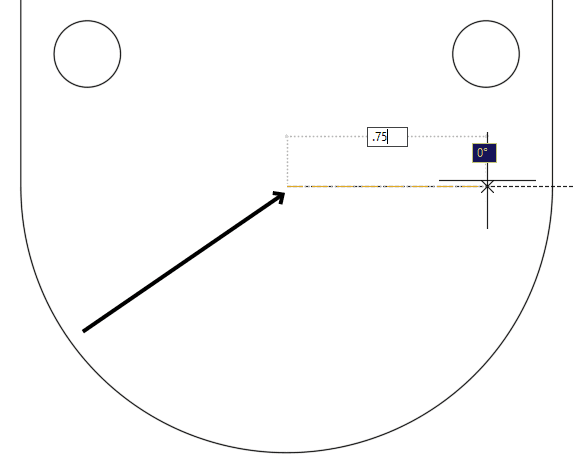
TIP: Click on the center point of the bottom arc to start the first axis of the ellipse.
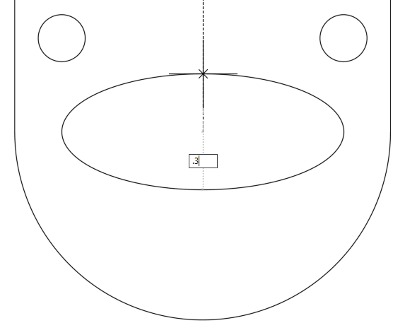
Pull up or down on the Y axis and enter a radius of .3 to complete the ellipse. The Axis, End (default), and Center options determine how you will make the first axis. The second axis is always a radius established from the center, unless you choose the Rotation option.
Use the Layer Previous Command to unfreeze the Text layer and bring back the Noble logo.
Now you will use the Ellipse tool
to complete the tube in the flagpole mount in the front view. The tube is angled at 45˚, so the ellipse you draw for the top of the tube must match the profile of a circle at a 45˚ angle. You can do that with the Rotation option on the Ellipse command.Type EL Enter to start the Ellipse command or select Axis, End from the Ellipse
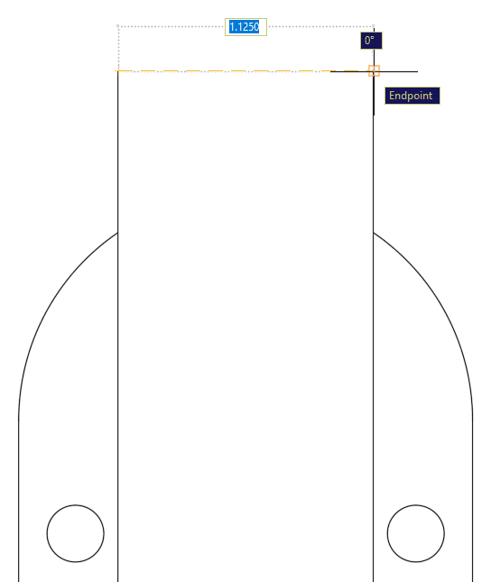
drop down menu in the Draw panel. Axis, End is the default setting for the Ellipse tool, so you won’t see it as an option in the Command Line. With the Axis, End setting you will establish the diameter of the first axis by clicking from end to end of the axis.Snap and click on the endpoint of either edge at the top of the tube and then click on the other endpoint to establish the first axis. Once the first axis is created, the Rotation option will appear in the Command Line. Press R Enter to activate the Rotation option.
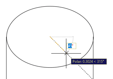
With the Rotation option selected, you can enter an angle for the second axis that will make the ellipse match the profile of a circle tilted at that angle. Because the tube of the flag mount is angled at 45˚, that will be the rotation angle for the second axis. Type 45 Enter or click on a 45˚ tracking line. You will see that the ellipse at the top of the tube coincides with the drawing of the side view.
To make the inner edge of the tube, press O Enter to start the Offset Command. Enter an offset distance of .0625 (1/16 of an inch) and select the ellipse you just made as the object to offset. Click anywhere inside the ellipse to specify a point on the side to offset. Press Enter or Escape to end the Offset command.
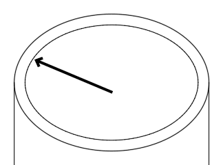
TIP: Offset the ellipse on the inside by.0625 to make the inner edge.
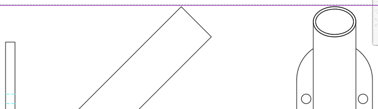
By comparing the side and front view, you can see that the ellipse you made for the top of the tube is what the circular tube tilted at 45˚ would look like from a front view.
Now you will use the Ellipse tool
to complete the tube with an Elliptical Arc. An Elliptical Arc is an arc made from a portion of an ellipse. When you choose the Arc option on the Ellipse tool, you will go through all the normal steps with the available options to complete an ellipse, but at the end of the process, you will click on two points of the arc to select what part of the ellipse will remain as an Elliptical Arc. The rest will be deleted.Press EL Enter to start the Ellipse command and then press A Enter to select the Arc option in the command line, or select Elliptical Arc from the Ellipse
drop down menu in the Draw panel. Snap to either of the endpoints at the bottom of the tube and repeat the steps you took to create the ellipse at the top of the tube, including using the Rotation option for the second axis with an angle of 45˚. The Command Line will now tell you to specify a start angle, this is for the creation of an Elliptical Arc. Because angles in AutoCAD are measured counter-clockwise by default, snap and click on the left endpoint and pull the cursor in a counter-clockwise direction and click on the opposite endpoint to complete the Elliptical Arc. Note how the line follows the cursor as you move counter-clockwise, as if you are cutting out a piece of cake.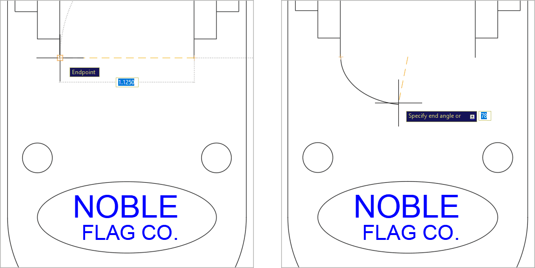
Using the Polygon Tool
Now you will use the Polygon tool
 to make the bolt in the side view. Type POL Enter, or select Polygon from the Rectangle drop down menu in the Draw panel, or click the Polygon button in the Draw Toolbar to start the Polygon command.
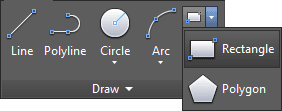
For number of sides, enter 6. To specify the center point of the Polygon, click on the center point of the arc at the end of the bracket on the front view, as shown below.
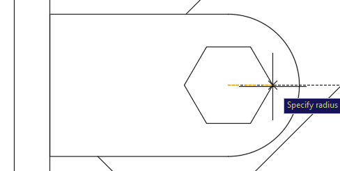
You will be prompted to select Inscribed or Circumscribed. By default, the Polygon will be based on an imaginary circle for which you will enter a radius. If Inscribed, the Polygon will be inside the imaginary circle, if Circumscribed, the polygon will be outside the circle. Pull left or right on the X axis and enter a radius of .3125, this will make it a standard 5/8 inch bolt. You can also use the Edge option of the Polygon tool
make the sides of the polygon a specific length, which will be covered in the next exercise.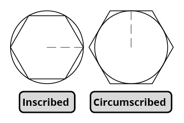
Close and save the file.