Multileader Tool
What This Tutorial Covers
Leader + Text
Connect notes to specific drawing elements.
Multileader Styles
Standardize arrow heads, text, and landings.
Align & Collect
Group leaders for clean annotation layouts.
Noble Desktop's AutoCAD Certification teaches 2D drafting, 3D modeling, and the production drawing workflow architects and engineers rely on every day.
Dive into this comprehensive AutoCAD tutorial that covers the use of Multileaders Tools and Commands, complete with exercise previews and overviews.
Exercise Preview
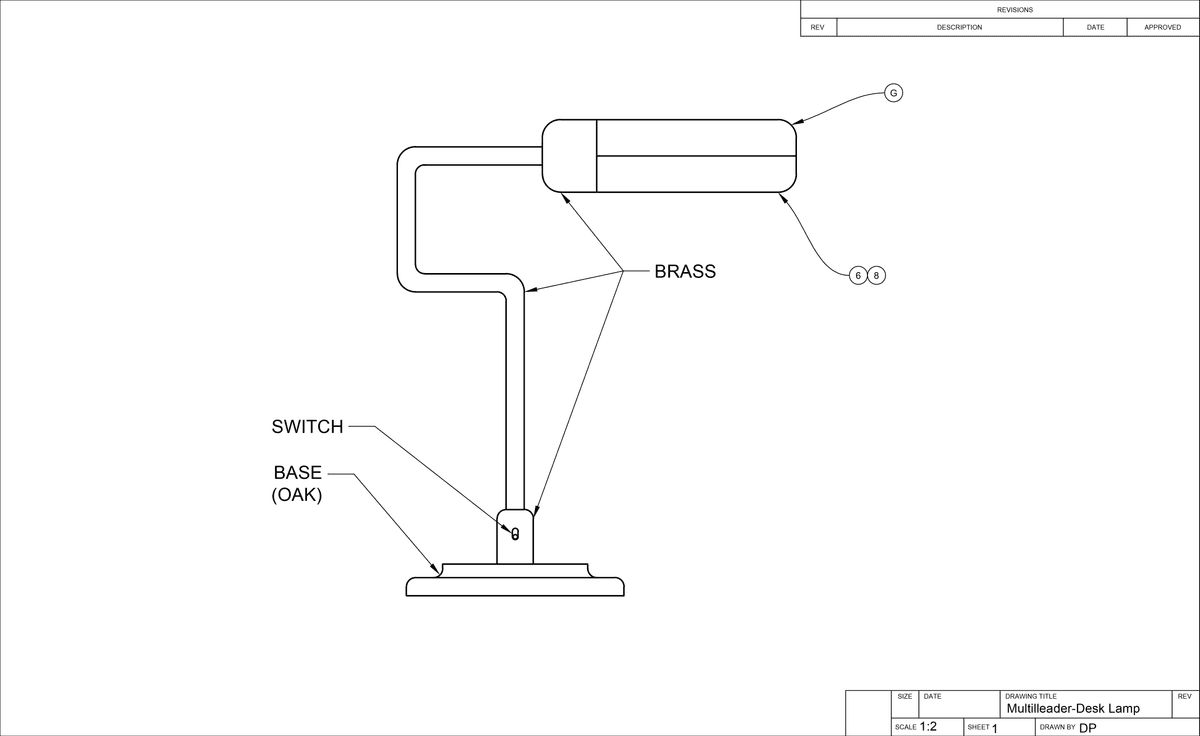
Multileaders
Open the file Multileaders-Desk Lamp.dwg. Switch to the B-Sized Layout and change the current layer to Text.
While in Paper Space, select Leader from the Multileader drop down menu in the Annotation Panel in the Home tab of the Ribbon or type MLEADER ENTER to activate the Multileader tool.
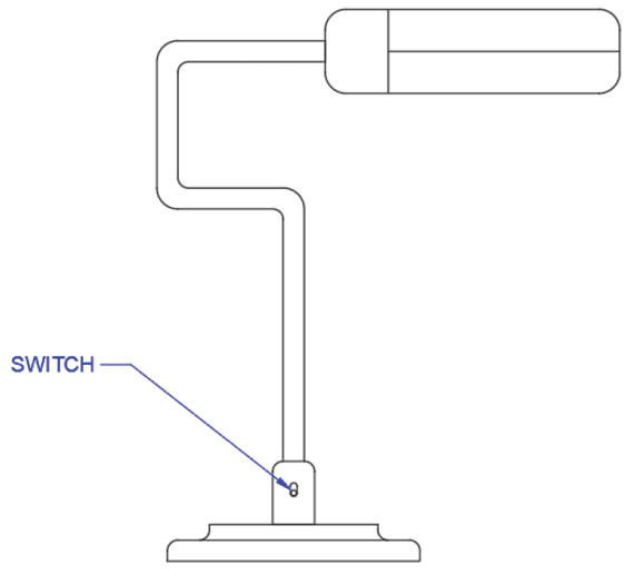
Click on any of the object snap points on the left side of the on/off switch right above the base of the lamp as shown below to place the leader arrow head. Even though you are in Paper Space, you can still snap to the Model with the Multileader tool.
Click in the area to the left of the lamp to place the text for the Multileader. The Text Editor Ribbon tab will appear. Type the word SWITCH in capital letters. Press Esc to exit the text editor and then press Enter to accept the changes.
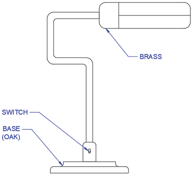
Now you will type two lines of text in the same Multileader. Repeat the Multileader command and click on the left edge of the base as shown below to place the leader. Place the text to the left of the lamp and type the word BASE and then press Enter to make another line of text. Type (OAK) and press Esc to exit the text editor and Enter to accept the changes.

Now that you have two Multileaders, you can align them with the MLEADERALIGN tool. From the Multileader drop down menu in the Annotation panel, select Align. Select both the SWITCH and BASE multileaders and press Enter. When prompted to Select Multileader to Align to, select SWITCH. A tracking line will appear emanating from the SWITCH mutlileader. Place the cursor below the SWITCH multileader until it snaps to the vertical polar tracking line and click so that the multileaders are aligned vertically.

Now you will add leaders to an existing multileader using Add Leader. This is an option of the MLEADEREDIT command which can be selected from the Ribbon. The ability to add multiple leaders to the same annotation is why the tool is called the Multileader command.
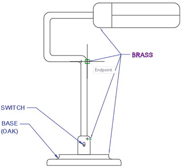
Create another mutlileader with the leader snapped to the point shown in the left diagram below. For the text, enter the word BRASS and then end the command.
From the Multileader drop down menu in the Annotation panel, select Add Leader. Select the BRASS multileader you just created and click on the points shown below in the diagram on the right to add three more leaders. Press Enter or Esc to end the command.
Create a Multileader with the text “BRASS” with the leader snapped to the point shown below:
Use Add Leader from the Annotation Panel to add 3 more leaders snapped to the points shown below:
One of the leaders you added in the last step is pointing to the base, which is made of oak, not brass. You will need to remove the leader. Select Remove Leader from the Multileader drop down menu in the Annotation Panel. This is also and option on the MLEADEREDIT command. Select the BRASS multileader. When prompted to Specify leaders to remove, select the leader pointing to the base. Press Enter to end the command. The leader will be deleted.
Select Remove Leader from the Annotation Panel to and select the leader shown below:
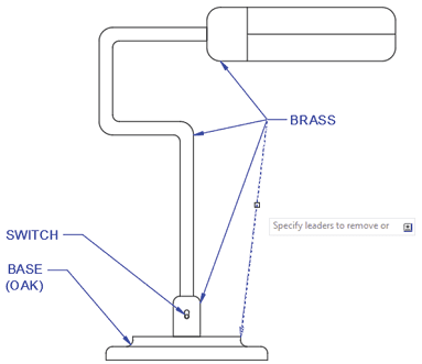
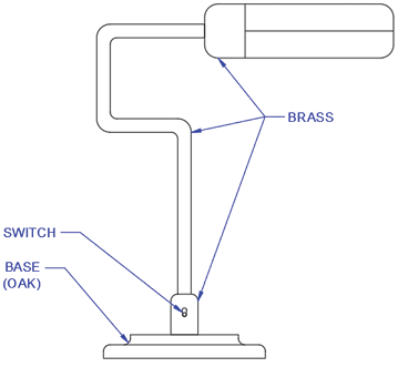
When you end the Remove Leader command, the selected leaders will be deleted:
Multileaders have many options that can be defined by assigning a Multileader Style. Now you will select a style that will used splined (curved) leaders ending in blocks rather than text. Creating styles will be covered in the Intermediate AutoCAD Class. Most of these options can also be set in the Properties Pallet.
Expand the Annotation panel in the Home pab of the Ribbon. You will see drop down menus for all style types, including Multileader Styles, which is the third menu from the top. Select the Tag Multileader Style.
Instead of text, the Tag Multileader Style ends in a block will be labeled with text that will be entered by the user when the multileader is created. This text label is called a Block Attribute. You will learn how to enter a value for the text in multileaders with Block Attributes in this exercise. Creating and inserting blocks with Block Attributes will be covered in the Advanced AutoCAD class.
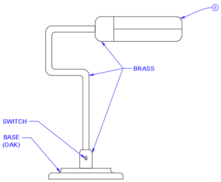
Now that the Tag Multileader Style has been selected, choose Leader from the Multileader drop down menu in the Annotation panel to start the Multileader command.
Click an object snap point on the upper section of the rounded rectangle at the top of the lamp as shown below. The Edit Attributes dialog box will appear. In Enter tag number field, type G and click OK. The leader will end in a circle with the letter G inside.
Sometimes more than one notation will be applicable the same object. If you are using a multileader style that ends in a block rather than text, you can select multiple multileaders and consolidate them into one leader for all the blocks.
While still using int Tag Multileader Style, create 2 multileaders pointing to the same object snap point on the lower section of the rounded rectangle that would house the bulb. Enter the numbers 6 and 7 as shown in the diagram below on the left.
From the Mleader drop down menu in the Annotation Panel, choose Collect to start the MLEADERCOLLECT command. You must select the multileaders to collect in the proper order. Select the Multileaders labeled 6 and 7 in that order and press Enter. The circular blocks will be collected onto one leader. Click the place the leader anywhere below the bulb.
Create two multileaders with Tag Style and enter the values 6 and 7. Make sure both leaders are snapped at the same point as shown below:
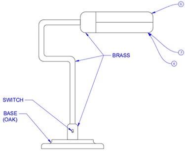
Start the MLEADERCOLLECT command. Select the multileaders 6 and 7 in order and press Enter. The circle blocks will be consolidated into one leader:

If you enter the wrong value for a multileader ending in a block with an attribute, you can edit the value by double–clicking on the block.
Double–click on the circle block containing the number 7. The Edit Attribute dialog box will appear. Change the 7 to an 8 and click OK. The 7 will be changed to an 8 in the multileader. Save and close the file.