Layout Tabs & Viewports
What This Tutorial Covers
Layout Tabs
Each tab is a printable sheet of paper.
Viewports
Windows that show model space at a chosen scale.
Sheet Setup
Page size, plotter, and layout once per tab.
Noble Desktop's AutoCAD Certification teaches 2D drafting, 3D modeling, and the production drawing workflow architects and engineers rely on every day.
Learn how to use Layouts and Viewports to scale and position your AutoCAD drawings perfectly for plotting and understanding the crucial differences between Model Space and Paper Space.
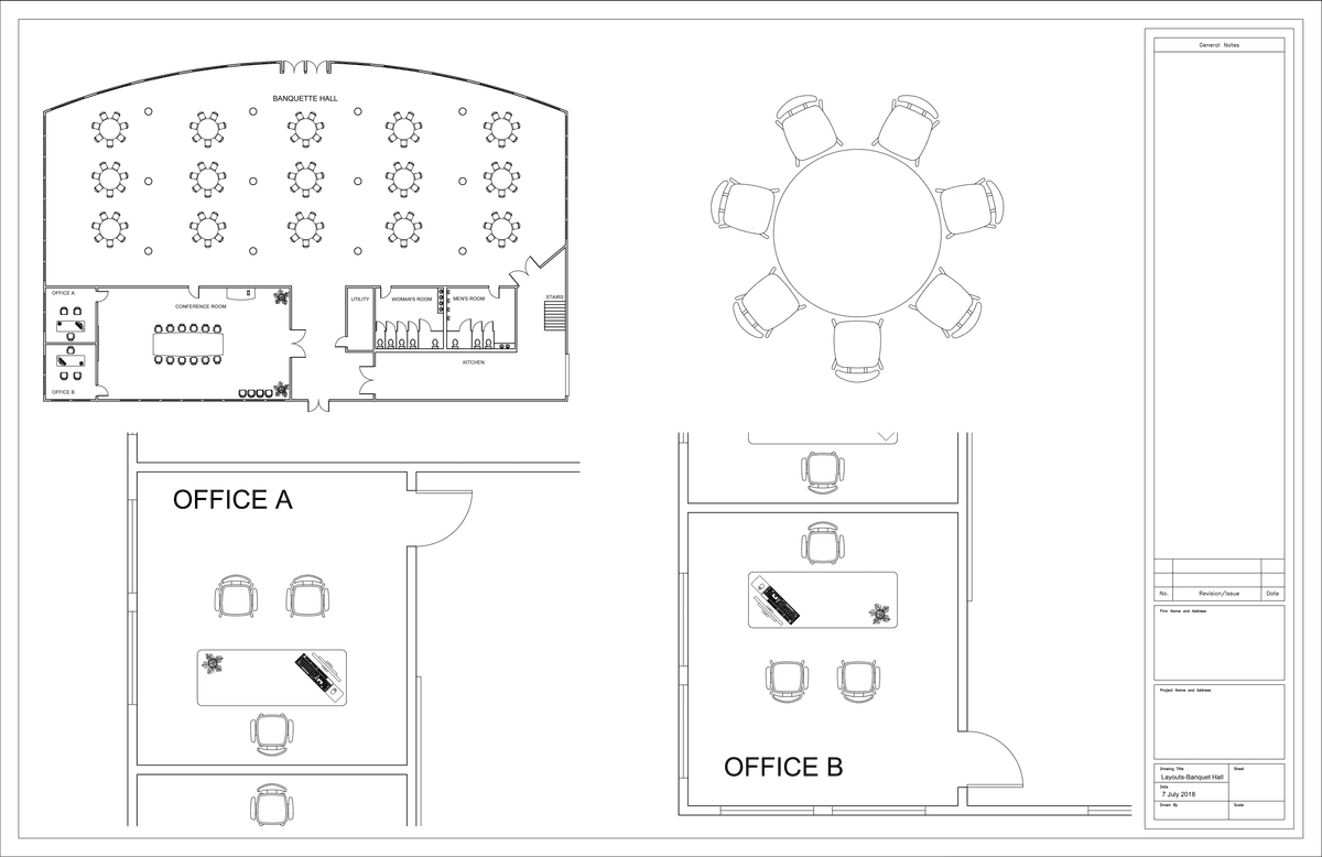
Exercise Preview
Using Layout Tabs
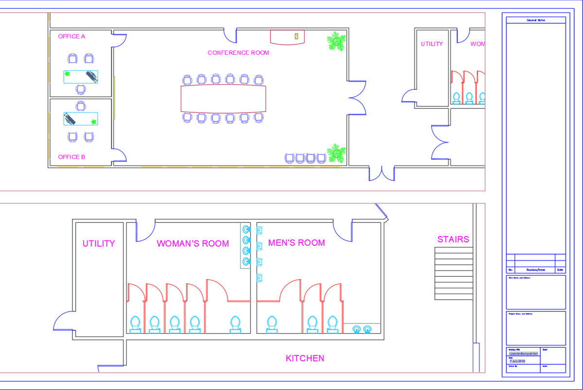
Open the file Layouts-Banquet Hall.dwg. The main drawing area in AutoCAD is in the Model tab. No matter how many objects you have in your drawing, it’s considered to be one model. Although you can zoom in and out to change magnification, all objects in the model have a scale of 1:1. You can plot from the Model tab, but it’s difficult to position or assign a specific scale to your drawing to be plotted precisely on a sheet. You can scale and position any area or areas of your model easily on a Layout tab.
NOTE: The Layout tabs are located at the bottom left of AutoCAD. You should see A-Sized and D-Sized layout tabs.
Click on the D-Sized layout tab at the bottom left side of the screen. A layout tab is an area sized to match paper sheets used for plotting, in this case D-Size (36x24in). It represents the sheet of paper the drawing will be printed on. Even as a digital file, like a.pdf, the sheet will need to conform to standard paper sizes and the drawing scaled and positioned accordingly. The Layout tabs are completely different areas from the Model tab. The objects in the Model do not exist in the Layout tab, and layout tab objects don’t exist in the Model tab, but the Model objects can be seen through viewports on a Layout tab.
When working in a Layout, objects that are part of the Model exist in Model Space and are only accessible through viewports. Objects that are on the Layout tab exist in Paper Space. The Model Space/Paper Space button
 at the bottom of the screen will allow you to switch between spaces.
Note that the Model Space/Paper Space button says Paper, indicating that you are in Paper Space. Click on the button to switch to Model Space. Zoom in and out with the scroll wheel on your mouse. Only the Model zooms within the viewport.
Click the Model Space/Paper Space button
to switch to Paper Space. Zoom in and out again with the mouse wheel. Now the entire layout will zoom because you are in Paper Space.You can also switch between spaces by double-clicking. Double-click inside any viewport to switch to Model Space. Double-click anywhere in the Layout Tab outside the viewports to switch to Paper Space.
Now you will assign a specific scale to the viewport. Switch to Model Space. You will see that the viewport is highlighted, which means it is selected. You must have a viewport in the Layout to enter Model Space. If there is only one viewport, then it will be automatically selected when Model Space is entered.
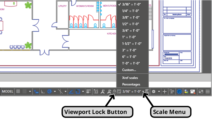
If a viewport is selected, the Scale menu will appear in the Status Bar. Double-click on the mouse wheel so that the model of the Banquet Hall zooms to the extent of the viewport and the model won’t zoom off the screen when you assign a scale. Expand the Scale menu and choose 3/16”=1’-0” as shown below. Because the viewport is selected, the Viewport Lock button will also appear in the Status Bar. The Viewport Lock button will lock the scale of the viewport so you won’t accidentally zoom in or out and change the scale, and the whole layout will zoom in both Paper and Modes spaces. Click the button to lock the viewport.
In most drawings, it is very important to assign a specific scale and lock to each viewport so that the measurements can be checked with a ruler or architectural scale on the printed sheet of paper.
Understanding Paper and Model space is crucial to using Layout Tabs and viewports effectively. Now you will compare objects in Paper Space and Model Space so you can see the differences. Switch to Paper Space. You will not be able to select objects in the viewport because they are in Model Space and the layout is set to Paper Space. Click to create a selection box around some of the objects in the Banquet Hall. No objects will be selected because they are in the Model Space. Click on the Title Block to select it. You are able to select the Title Block because it is in the Paper Space.
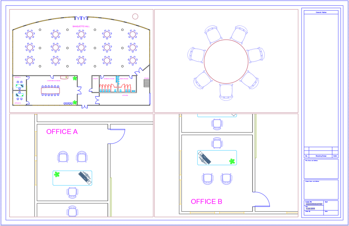
While still in Paper Space, create a circle with a radius of 9/16” in the empty area outside the Banquet Hall in the upper right corner of the viewport. Switch to Model Space and create another circle next to the one you just made with a radius of 3’. Even though the circle in the Model Space is much larger than the circle in Paper Space, they will appear to be the same size because the model in the viewport is scaled to 3/16”=1’-0” and the Paper Space scale is always 1:1.
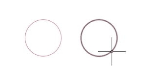
Notice in the image above that both circles appear to be the same size.
Click on the A-Sized Layout tab. In this tab you will be able to see the circle that you made in Model Space, but not the one in Paper Space because that only exists in the Paper Space, in the D-Sized Layout tab. Switch to the Model tab. Here again you will see the Model Space circle only. Delete the circle. Switch back to the D-Sized Layout tab. Only the circle in Paper Space remains because you deleted the other circle in the Model tab. Objects in Model Space are accessible wherever the Model is visible, but objects in Paper Space are only accessible in the Paper Spaces of the Layout tabs in which they were created. Switch to Paper Space if necessary and delete the Paper Space circle you created.
Some Title Blocks are automated with Block Attributes and Fields. Block Attributes are text labels that can be applied to individual instances of blocks. Fields are lines of text that display certain information and will automatically update if the information changes, like the file name or date.
Double-click on the Title Block. Because this block has Attributes, the Enhanced Attribute Editor will appear if you double-click on it. This will allow you to enter information into the Title Block without having to manually type it with the text tools.
The values for date and drawing name are Fields so they are entered automatically. If you click on the Sheet Number in the Prompt column of the Attribute tab, you will see that the Value area is blank. Enter a value of 1. Click on Drawn By in the Prompt column and enter your initials for the Value. Use the scroll bar to scroll up in the Attribute tab and click on the Scale prompt. Enter a Value of 3/16”=1’, and click OK.
Zoom in on the lower right section of the Title Block. You will see that your initials and the sheet number will appear in the Title Block as you entered them in the Enhanced Attribute Editor.
NOTE: Creating blocks with Attributes and Fields will be covered in the Level 3 class, but you may encounter files with automated title blocks in which case you’ll only need to double-click on them and enter values for whatever attributes have been added.
In the next section you will learn how to manually enter information into title blocks with the text tools.
Now you will make a copy of the D-Sized Layout so you can make another sheet focusing on different parts of the model. If you create a new Layout, it will have the default blank Layout setup, an 11x8.5 inch sheet with no title block or plotter assigned. One of the major benefits to using Layout Tabs is the title blocks, text, all of the settings that can be saved with it so you can plot without having to choose options.
Right-click on the D-Sized Tab, the actual tab at the bottom of the screen with the text that says “D-Sized”. From the right-click menu select Move or Copy. In the Move or Copy dialog, select (move to end) so the copy will be the last tab at the bottom of the screen. Check Create a copy and click OK.
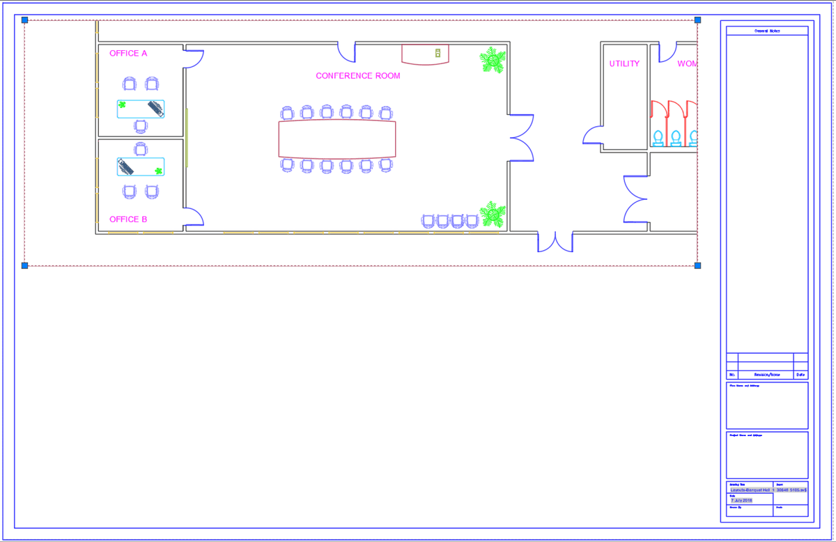
Switch to the new D-Sized (2) Layout. The viewport, as an object, exists in Paper Space. If you highlight a viewport in Model Space, you’re activating it so you can change the view, but you haven’t really selected it so it can be resized, moved or deleted. If you select a viewport in Paper Space, grips will appear like any other object so you can manipulate the viewport. Make sure you are in Paper Space and click on the edge of the viewport to select it. Click the bottom center grip and shrink the viewport so it only takes up the top half of the layout. Double-click inside the viewport to switch to Model Space. Zoom in on the Conference Room. Choose a scale that best fits the area. You may have to experiment with several scales and reposition with the mouse wheel. Lock the viewport to maintain position and scale.
Now you will create a second viewport in the same layout. Switch to the Layout Ribbon tab. The Layout tab in the Ribbon only exists when you are in a Layout. From the Viewport drop down menu in the Ribbon, select single. This activates the Single Viewport option of the VPORTS Command so you can make rectangular viewports. Click to create a new viewport taking up the bottom half of the Layout in the same way you would make a rectangle. Use grips to make adjustments if necessary. Zoom in on the bathrooms. Scale and lock the viewport.
Use Move or Copy from the D-Sized (2) Layout tab menu to duplicate the Layout. Switch to the new Layout copy and select and delete the existing viewports from the Paper Space. Now you will use the Viewports Command (VPORTS) to make multiple viewports at once. Type VPORTS Enter. For configuration, select Four Equal. For Viewport Spacing, enter .125 (1/8”). With the cursor, click to create one large viewport that encompasses the entire layout. It will be automatically split into four equally sized viewports.125 inches apart. Position, scale, and lock each viewport, focusing on whatever areas of the Banquet Hall you see fit.
Keep the file open. You’ll continue using it in the next exercise.