The Fillet Command
AutoCAD Drafting Checklist
Wall lines on WALLS, dimensions on DIMS — never on layer 0.
Define them once in your template; reuse across projects.
Keeps file sizes manageable and exchange clean.
Project moves between machines without breaking references.
Noble Desktop's AutoCAD Certification teaches drafting, layouts, blocks, and dimensions.
Dive into this comprehensive AutoCAD tutorial that details the application of the Fillet command to create a more aesthetically pleasing desk lamp design.
Exercise Preview

The Fillet Command
Open the file Fillet-Desk Lamp.dwg.
Press F Enter to start the Fillet command. By default, the fillet command will only round off one corner and then the command will end. In the Command Line you will see a Multiple option. With this option you can fillet as many corners as you’d like and change settings as needed without ending the command until you press ENTER. While still in the Fillet command, press M Enter to activate the Multiple option.
You will need to set a radius for the Fillet command. Press R Enter to select the Radius option from the Command Line. Enter a radius of .5. You can press R Enter to change the radius at any time without exiting the Fillet command because you selected the Multiple option.
The bulb housing of the lamp was made with the Rectangle tool, so it is a Polyline. You can use the Polyline option of the Fillet command to fillet all the corners of a polyline at the same time. Press P Enter to choose the Polyline option.
Click on the rectangle at the top of the drawing to fillet all four corners of the polyline at the same time. Stay in the Fillet command for the next step.
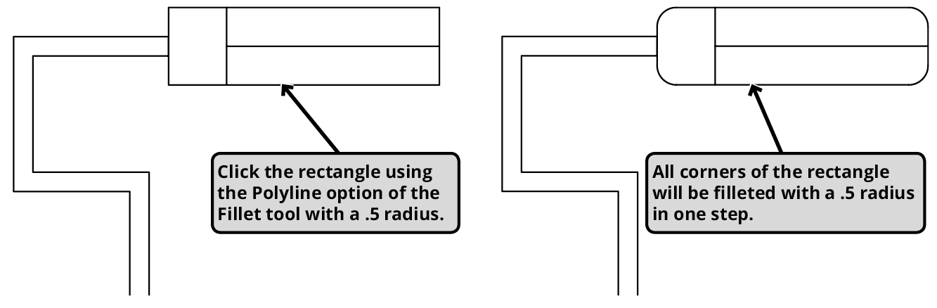
Once the Polyline option has been used, the Fillet tool will resume rounding one corner at a time. Click the two outer edges of the upper right corner to round it out. The Fillet command will still use the radius of.5 that you entered earlier.
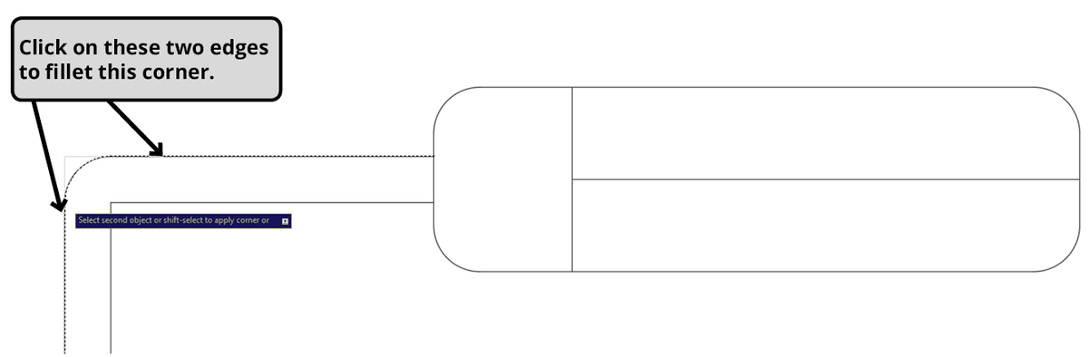
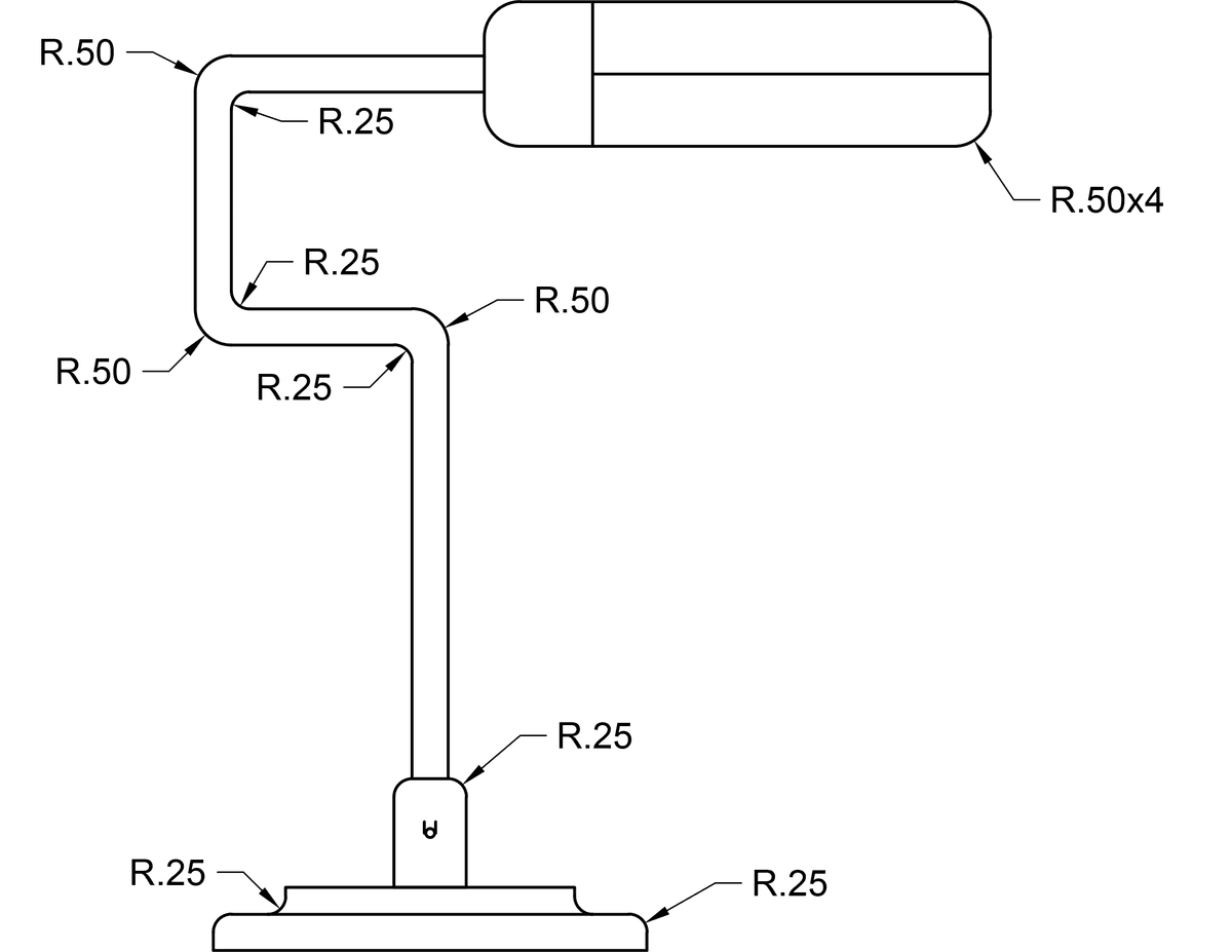
Repeat the process from the last step to fillet all the other corners with a radius of .5 as shown in the diagram below. Then press R Enter to change the radius to .25 to fillet the remaining corners. Stay in the Fillet command for the last step.
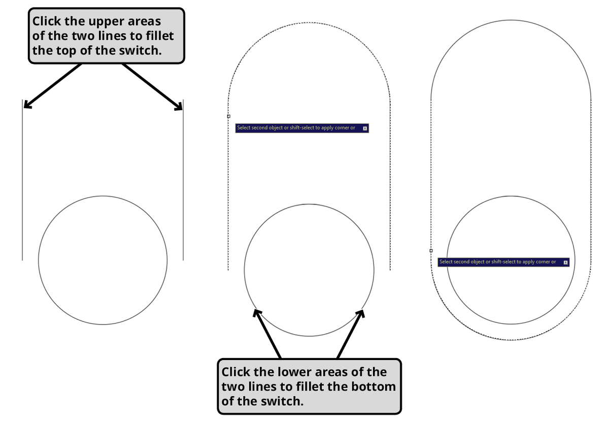
Zoom in toward the base of the lamp on the small circle with horizontal lines on either side. You will be able to make curved edges connecting the lines even though they are not touching. Click on the tops of both straight lines and then the bottoms as shown below. The result will be a capsule shape around the circle to make a switch for the lamp. Note that because the lines aren’t touching, the distance between the lines will act as a diameter for the fillet, so any radius entered by the user will be ignored. Press Enter or Escape to end the Fillet command.
Close and save the file.