Mechanical Hatching
Essential AutoCAD Commands
OFFSET
Create parallel lines at a set distance — fundamental drafting move.
TRIM / EXTEND
Clean intersection of geometry — speeds up every drawing.
MIRROR
Reflect geometry across an axis — symmetric layouts in seconds.
ARRAY
Rectangular or polar duplication — handles repeating elements.
Noble Desktop's AutoCAD Certification teaches drafting, layouts, blocks, and dimensions.
Dive deep into the intricacies of AutoCAD with this detailed tutorial that covers the use of the Hatch command, Cross Section Hatching, and more.
Exercise Preview
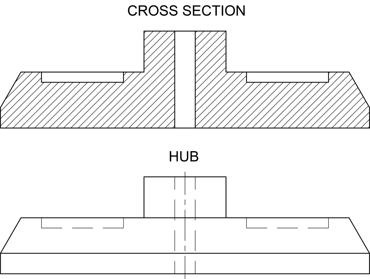
Cross Section Hatching
Open the file Hatch-Hub Section.dwg.
Start the Hatch command by pressing H Enter. You can also press the Hatch button
 in the Draw Panel or Toolbar. The Hatch Creation Ribbon tab will appear, which can allow you to set options for the hatch before it’s created. When prompted to Pick internal point, click on the two enclosed areas in the Cross Section indicated in the diagram below and press ENTER. When selecting areas to hatch, by default you must click inside closed areas created by objects of any type. If there are gaps, you can set a Gap Tolerance, which will be covered in the next exercise. You can click in multiple areas, but when you press ENTER it will still be considered one hatch and will be selected as if it were a single object. Be careful not to click in the same area more than once, or you will create another hatch over the one you already created. For this exercise, you will be using the default hatch pattern (ANSI31). In drafting, this pattern is used for indicating cross section surfaces such as the cross sectioned object in this exercise. You will learn how to choose other patterns in the next exercise.
Select the Hatch you just created. The Hatch Editor will appear. Expand the Properties Panel in the Hatch Editor. You will see a Layer drop down menu that will allow you to change what layer the hatch is on without changing the current layer of the drawing. Change the layer from Object to Hatch. The Cross Section Hatch you created will be moved to the Hatch layer and will change to the color of that layer.
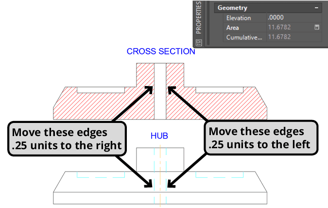
With the hatch selected, look at the area in the Properties Pallet, it will be 10.4952. By default, hatches are associative, which means that if the objects that defined the hatch are repositioned, the hatch will change is size and shape to match the new area defined by the objects as long as it remains closed. Use the Move command to move the vertical edges of the hole at the center of the hub inward by.25 inches for each edge in both the Cross Section and Hub views. The hole will be made narrower and the hatch will change shape to match the new areas. The centerline in the Hub view will shift as you move the edges because it was made with the Centerline tool, so it will always be centered between the two lines. Select the hatch again and look at the area in the Properties Pallet. Now it will be 11.6782.
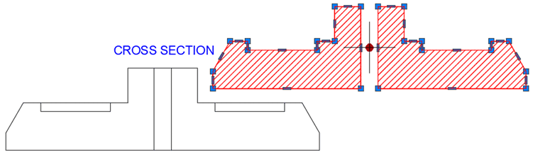
Although hatches are associative, they are intendant objects Hatches can become disassociated from objects if you click to un-highlight the Associative button in the Hatch Editor ribbon or by removing the hatch from it’s associative objects. The disassociated hatch will have grips like any other object. Once a hatch is disassociated, it can’t be re-associated again.
Select the hatch and click on the round grip in the center and move the hatch away from the objects. Note the grips around the edges of the hatch. Press CTRL–Z to undo the move so the hatch will remain associated with the hub.
Save and close the file.