Measurement Tools
What This Tutorial Covers
Distance & Radius
Quick on-screen measurements between points.
Area Calculations
Calculate enclosed regions for takeoffs.
Quick Measure
Hover-driven inspection of nearby geometry.
Noble Desktop's AutoCAD Certification teaches 2D drafting, 3D modeling, and the production drawing workflow architects and engineers rely on every day.
Learn to effectively use measurement tools in AutoCAD to obtain crucial information such as area, distance, and angle from a drawing with this comprehensive tutorial.
Exercise Preview
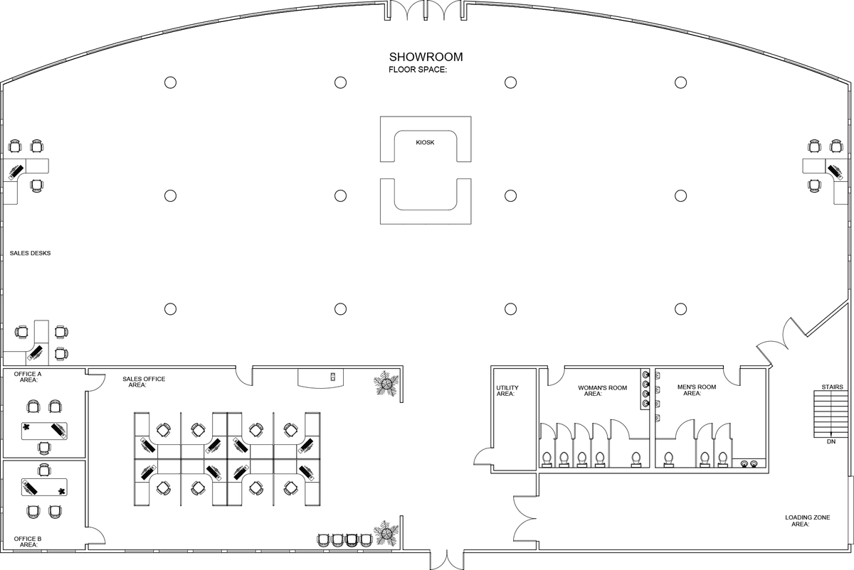
Using Measurement Tools to Get Info About a Drawing
Open the file Measurement Tools-Furniture Showroom.dwg.
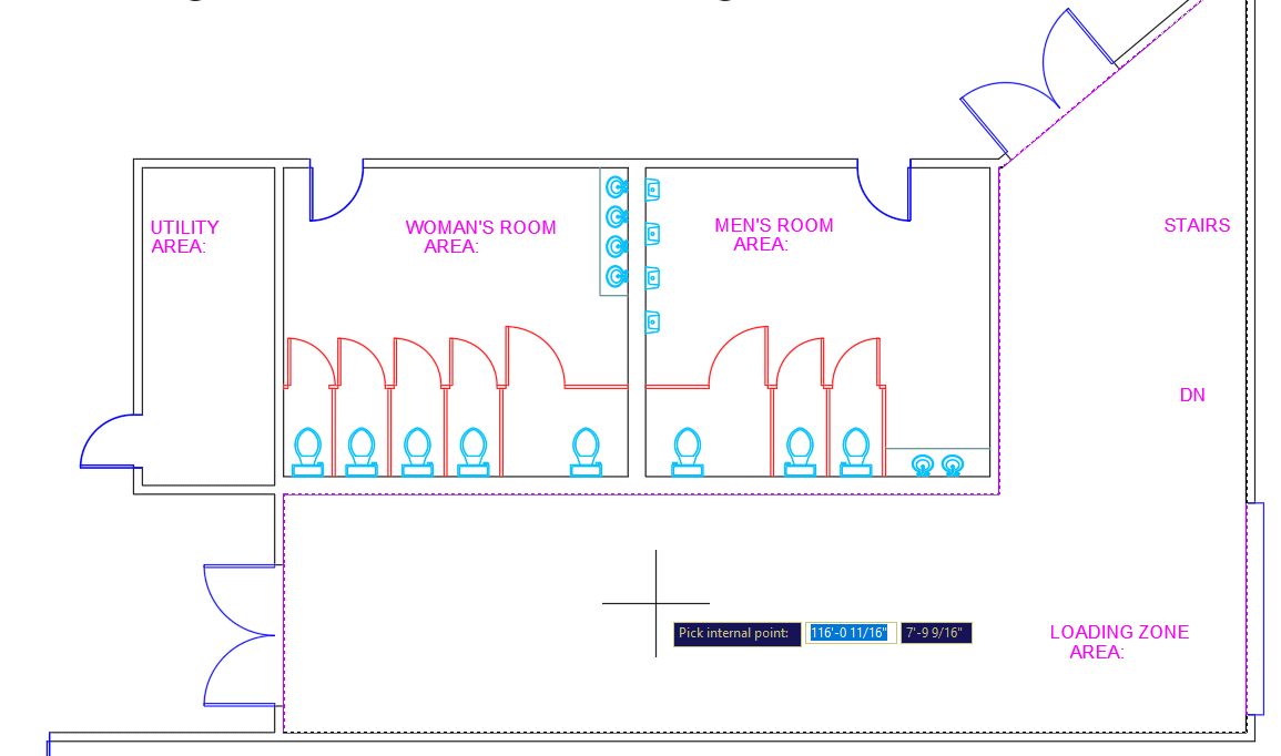
Because this is a furniture showroom, it’s necessary to know how wide a hallway is coming out of the loading area. In the Utilities Panel, expand the Measure
 drop down menu. You will see all the options of the MEASUREGEOM Command. Click the Distance button. You can also type in the alias of DI Enter.
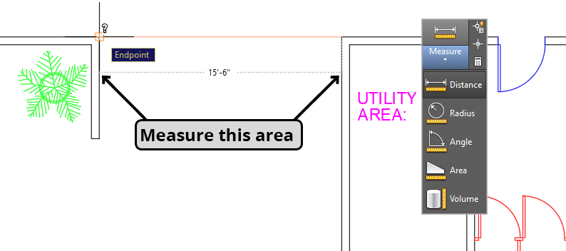
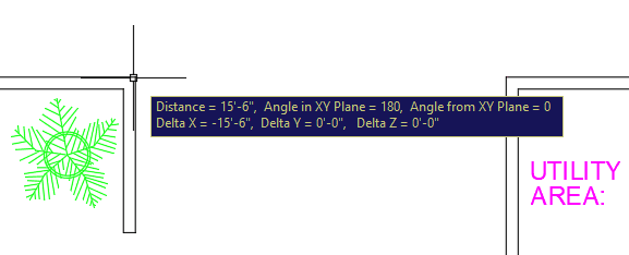
With the Distance tool, you can snap to any 2 points to get a measurement of the straight line distance between the points. Zoom in on the entrance to the hallway between the Sales Office and the Utility closet. Click on the corner endpoints on both sides of the hallway as shown below. The distance will appear in the Dynamic Input (as shown below) and in the Command Line.
If you zoom in on the Kiosk counters, you will see that the inner corners are rounded. It may be useful to know the radius of the rounded corners for cutting carpet or tile. Zoom in on any rounded inner corner of the Kiosk. Select Radius from the Measure
drop down menu. Click on the edge of the rounded corner and the radius will appear in the Dynamic Input and the Command Line.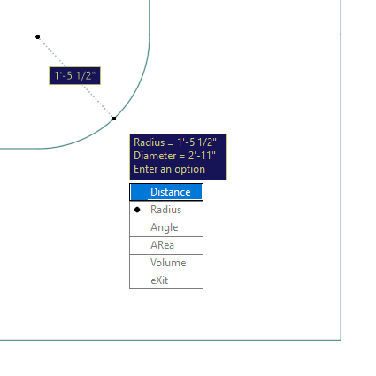
The section of wall in the lower-left corner of the Showroom where the double doors exit the Loading Zone is tilted to an angle that doesn’t conform to the standard polar tracking angles. To find out the angle of the wall, select Angle from the Measurement menu, and click on both of the inside edges of the upper corner of the walls as shown below. With this tool you will click on the lines themselves, and not to object snap points. The angle of 50˚ will be displayed.

If you need to know the exact coordinate of a point or object, you can use the Identify Point tool
 by pressing the icon in the Utility Panel, or typing ID Enter. The Identify Point tool is its own command and is not an option of the Measuregeom tool.
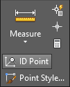
Start the Identify Point command and click on the center point of the lower left circular column in the Showroom, the coordinate of 30
',43'will be displayed. Now you will know exactly where to place the first column so you can use the Array tool to create the rest, which you will do in a later exercise. Note that the lower-left corner of this building has been placed at point 0,0. If grid coordinates will be important to your drawing, make sure that your first object is placed on a specific point on the XY grid, usually 0,0.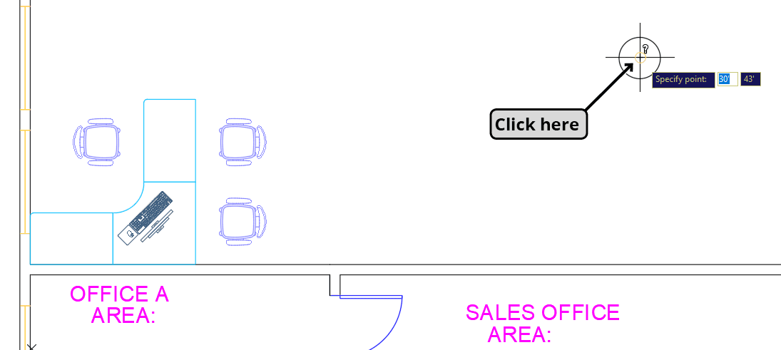
TIP: Click the on the center point of the lower-left column with the Identify Point tool.
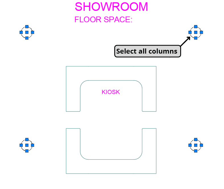
Now you will use the LIST command to get more information about the columns. Without starting the command, select any of the columns. Right–click and choose Select Similar from the menu. Now that all of the columns are selected, start the LIST command by clicking the List button in the Inquiry Toolbar or type LI Enter. The Text Window will appear. The Text Window displays all of the text that has appeared in the Command Line since the file was opened. If there is too much information to fit in the Text Window during the List command, you may have to press Enter to see the next block of text. You can scroll back to see any previous Line information. This is a great way to recall and record information and measurements from earlier commands such as distances, angles or areas. You will see that all of the information for the columns is in the Text Window, including diameter and center point coordinates for placement and construction when they are built. You can highlight and copy any text in the Text Window so you can paste it in an email or document. If you Right–click, you will see an option for pasting text to the Command Line to repeat steps from previous commands. The Text Window opens whenever you use the List command, but you can open and close it at any time by pressing the F2 function key on your keyboard. Click the X on the Text Window and press Enter or Escape to end the List command.
TIP: Select all of the columns with Select Similar (as shown by the arrow below) and then start the List command.
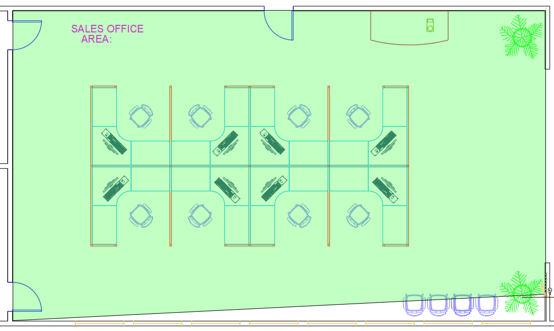
One of the most important pieces of information you might need from a drawing is area. There are several ways to determine area, each with its own pros and cons. Select Area from the Measure drop down menu in the Utilities panel or type AA Enter. Click on the four inner corners of the Sales Office. You’ll see a green field indicating the area being covered. After clicking all 4 points, press Enter. It’s not necessary to click back on the first point to complete the action, and it doesn’t matter where the cursor is after you click the last point, when you press ENTER, you will get an accurate reading of the area and the perimeter in the command line, in this case 1760 square feet. The advantage of using the Area tool is that you can click around a perimeter of an area without any objects interfering, even if there are open gaps in the perimeter. However, you cannot get an area with a curved edge by default, or subtract the areas of interior objects, and there can be a risk of clicking on the wrong snap point and getting inaccurate results if the perimeter is too complex. There are options in the Area tool for getting areas of closed polylines with curved segments and subtract interior polylines but most users find it easier to create a Hatch or Boundary and check the area in the Properties Palette.
Double–click on the text that says AREA:, and type 1760 sq ft. after the colon. Press Enter twice to enter the text and end the Single Line Text tool. Text will be covered in more detail in a later chapter.
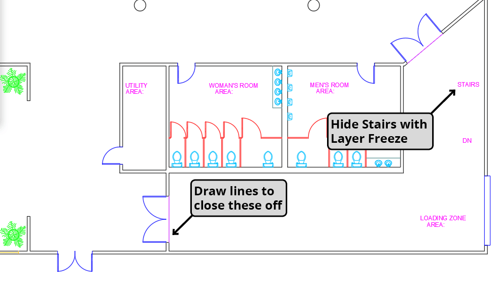
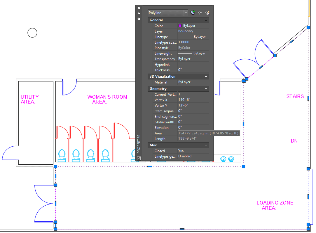
Now you will create a polyline around the perimeter of the room with the Boundary tool, so that you can see the area in the Properties Panel. Change the current layer to Boundary. Zoom in on the Loading Zone in the lower-right corner of the building. The Boundary tool only works on closed borders, so you will need to close off the door openings as shown in the diagram below. You do not want the boundary to be made around the stairs. Start the Layer Freeze command and click on the stairs. The Stairs layer will freeze and the stairs will disappear.
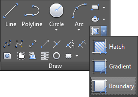
The Boundary tool is a quick and easy way to make polylines based on existing closed borders. These polylines can be used to measure areas with the Properties Palette. Type BOUNDARY Enter or select Boundary from the Hatch drop down menu in the Draw Panel, as shown below.
The Boundary dialog box will appear. Uncheck Island detection. Island detection will also make polylines around objects inside the boundary, it’s usually best to keep it unchecked.
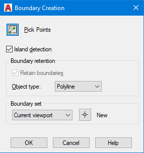
Click on the Pick Point button, and then click anywhere inside the Loading Zone. Press Enter to accept the boundary and end the command.
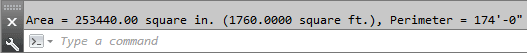
Select the polyline you just created with the Boundary tool. Scroll down in the Properties Palette to see the Area and the length, which is also the perimeter. The area will be displayed in square inches, but if you hover over the area with the cursor, Double on the AREA: text and type in the area as you did in the Sales Office.
Now you will create a Hatch to measure the area of the Showroom. A Hatch is a pattern you fill an area with, like brick or tile. Like the Boundary tool, you can simply pick a point within an enclosed space. Because hatches fill the area, island objects within the Hatch will be excluded, and thus subtracted from the total area displayed in the Properties Palette. Use the Layer Freeze tool to hide the doors and all of the furniture in the Showroom except for the Kiosk counters. Change the current layer to Hatch. Use the Line tool
 to close off all the openings, including the hallway between the Sales Office and Utility room.
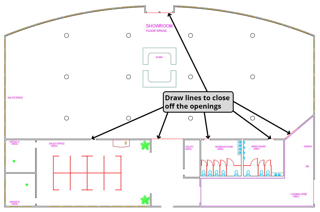
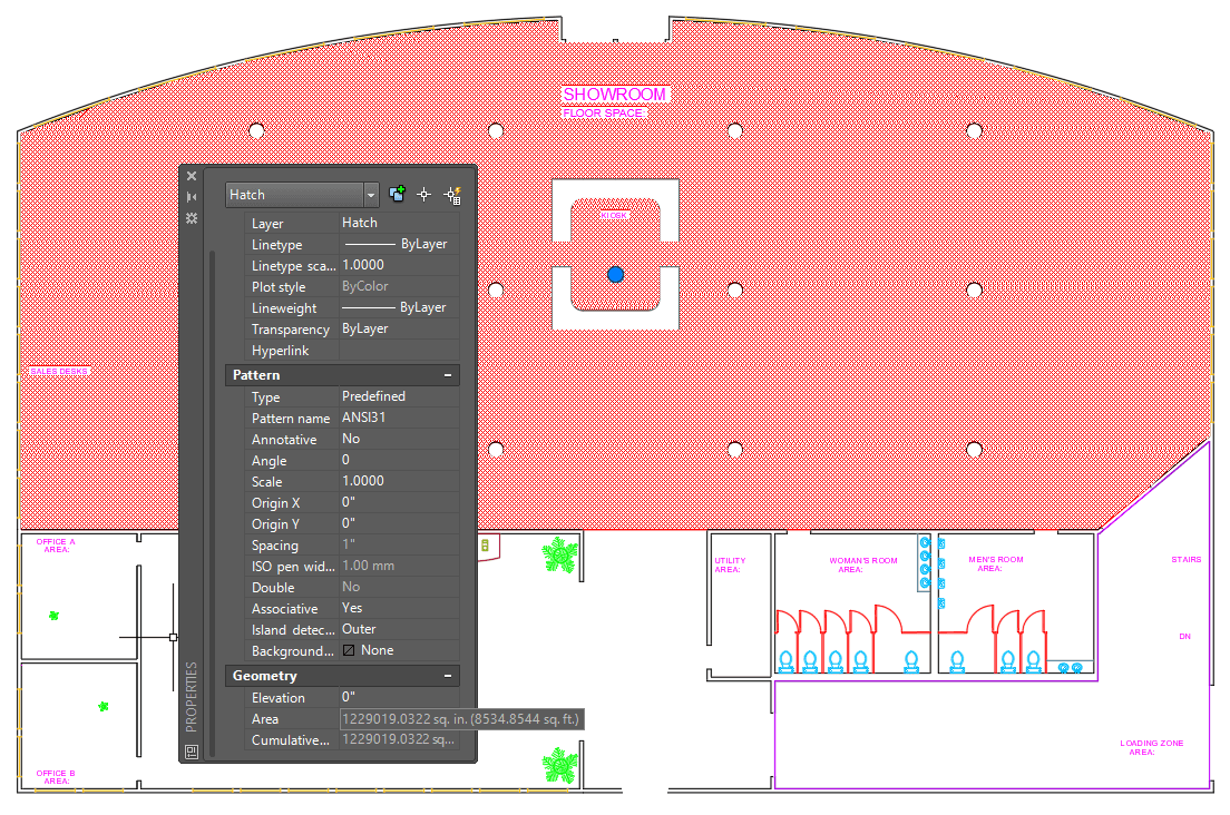
Click the Hatch button in the Draw Panel or type H Enter. The Hatch Editing Tab will appear in the Ribbon. Because you will only be using the hatch to determine the area, the options don’t matter. You’ll delete it when you’re done. You will be prompted to pick a point. Click anywhere in the Showroom, except inside a column or Kiosk counter. The Showroom will be filled with the default hatch pattern, which will appear to be a solid color unless you zoom in very close. Press Enter to accept the hatch and end the command. Note that the columns and kiosk counters are excluded from the hatch and will not be added to the area. The Hatch command will also leave an area around the text so it can still readable, but the text can be moved or deleted without corrupting the hatch, and the text won’t affect the area total. Click on the hatch to select it. Once the hatch is selected, look in the geometry section of the Properties Palette to see the area. The perimeter will not be displayed when you select a hatch. Double–click on the AREA: text in the Showroom and type 8535 sq. Ft. (rounded up from the 8534.8544 as indicated in the Properties Pallete). Delete the Hatch. Use the Layer Previous tool to thaw the previously frozen layers, then use the Layer Freeze tool to hide the remaining lines on the Hatch and Boundary layers. If time permits, find the area of each room and enter totals in the AREA: text objects.
Save and close the file.